
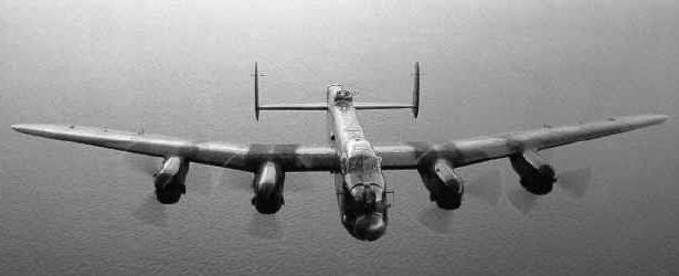
To begin the story of the Lancaster Airframe, we must go back to the Manchester, as this is where the venerable Lanc’ started life.
In September 1936, the Air Ministry issued specification P13/36. This was to be a twin engined medium bomber with dive-bombing capability. AVRO, among other British Companies, answered this specification with a submission to the Ministry in January 1937. The aircraft was called-Type 679, later to become the Manchester.
The Manchester represented an enormous challenge to AVRO, as they had no experience of all-metal stressed skin construction. Nor had they attempted such a large aircraft before. The initial design was to have a wingspan of 72ft, and a fuselage length of 69ft. All of the bomb load was to be carried in the fuselage, and all fuel and oil to be contained in the wings. The estimated gross weight, was 37,777lbs. The dihedral angle on the outer wings was 7 degrees. The tailplane carried twin fins, although this was probably due more to tradition rather than technical reasons.
The heart of the Manchester, was the combined wing & fuselage centre section.
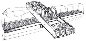
The structure of the wing centre section was based on two spars of simple construction, both consisting of mass booms and plate webs. Running at right angles were two fuselage longerons which formed the basis of the cabin floor & the bomb bay roof. The aircraft needed to be “simple” to aid easy manufacture, and a high rate of production. Light alloy was used for the manufacture of most components, and stampings & pressings were used to minimise hand fitting work.
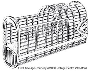
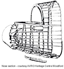
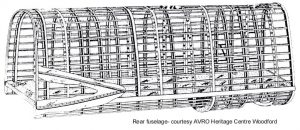
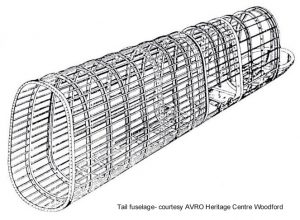
The fuselage was a light alloy monocoque structure, with skins flush riveted to a framework of formers & stringers. It comprised four sections, making for easy transport, both when new, and after a repairable accident.
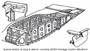
In addition to its two spar construction the wing incorporated ribs built of plate webs and drawn angle flanges. The skins were flush riveted and skin overlaps were minimised.
Flying control surfaces were to be ball bearing mounted, operated by cables sized to minimise circuit stretch.
After acceptance by the Air Ministry, a contract was issued for the manufacture of two prototypes. On 1st July 1937, a further contract was issued, for the supply of 200 production aeroplanes. In January 1937, AVRO had already decided, that changes needed to be made to the design. This was quite common, at the prototype stage. The fuselage length changed to 69ft 4.5ins, and changes were made to the shape & skin curvature, to make design and manufacture more straightforward. From a previous 72ft, the wingspan went up to 80ft 2ins. Tailplane span remained at 28ft, but the fins and rudders were moved fully outboard. The aerofoil section now selected was the NACA 23000 series, 23018 over the centre section, 23018 reducing to 23009 for the outer wing. Avro production experience up to this time, was largely as a woodworking firm. A production contract for 1,000 Bristol Blenheim Aircraft in 1937, gave the company valuable experience of stressed skin construction. Avro were breaking new ground, in the milling of Hiduminium L40 spar sections of the size required for this aeroplane. The main centre section incorporating the parallel cord wing centre section, formed the heart of the aircraft. The wing incidence was set at 4 degrees up to the fuselage centre line.
A high proportion of the fuselage length was of constant cross section, with heavier frames at the transport joints. This reduced the amount of tooling required. When fully assembled, the bomb bay was 33ft 3ins long, by 5ft 6ins wide. Bomb bay doors were 2ft 8ins wide. Operated hydraulically with sequenced hydraulic locks.
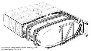
As with the fuselage design, the wing was divided into transportable sections. The 28ft 6″ parallel wing centre section passed through the main fuselage section. The undercarriage bays & the Rolls Royce X-24 Vulture engines were contained in nacelles mounted at the outboard ends of the wing centre section. the depth of the parallel section was 2ft 11″, 18% thickness/chord ratio being selected at the best compromise between airframe strength & aerodynamic drag. The fuel tanks were mounted between the wing spars, & held in place by simple strap & turnbuckle attachments. Access was gained from the underside of the wings.
The outer wing was a straight tapered two spar assembly from rib number 22 to rib number 5. Span of the outer wing structure, was 21ft 5.5″.
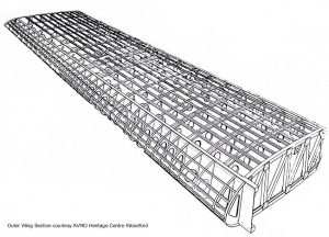
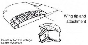
At the root-end transport joint was another braced frame rib. Outboard of this were all pressed ribs, with flanged lightening holes, and riveted vertical stiffeners. The outer wing tapered from 18% thickness/cord, down to 9%. The main spar was likewise tapered. Detachable wing tips of 4ft 6″ span were added to the outer wing at rib 5.
The wings had detachable trailing edges incorporating the flap assy, and ailerons. The centre section had a hinged, detachable, leading edge, for easy access. The flaps were simply hinged in two sections to accomodate the dihedral change and were operated by a single push-pull tube, with a series of links. The aileron hinges were externally mounted. Engine subframes & undercarriage attachments were bolted to the front spar/engine rib joints in the centre section. The engine subframe used a pin-jointed tube & socket structure.
The tailplane & fin layout made for simple construction & attachment. With a width of 28ft, the tailplane was made in two halves. It was of a two spar and pressed rib construction, with light stringers on the same principle as the wing. It used constant section spar boom extrusions & tapering plate webs. The spars extended beyond the aerodynamic surface to secure the fin posts at simple bolted joints. The prototype fins were 8ft 10″ tall. The rudders & elevators were carried on hinge brackets. The flying control surfaces were all metal, the elevator having a manually operated trim tab, as did the rudder.
To Be Continued….